Product Details
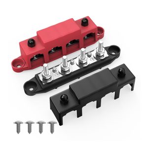
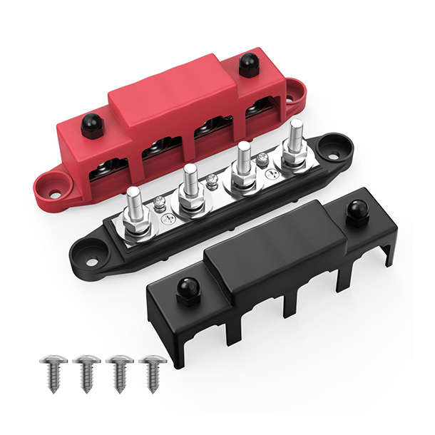
BB400-T4M10S3-C-BR-2 combines 4 x M10(3/8″) studs with 3 screw terminals on a 400 A bus bar. The mixed connection layout gives cable lugs and smaller terminated conductors their own landing positions, helping installers organize a common supply or return connection. Black and red versions share the same connection layout.
BB400-T4M10S3-C-BR-2 / mixed terminal configuration.
- 01 Separate landing points on a common bus
4 M10(3/8″) studs and 3 screw terminals distribute connections along the bar rather than concentrating every lug on one post. These positions share a bus; they are not separately isolated circuits. - 02 A covered terminal area
The protective cover helps shield the connection area from incidental contact. Provide sufficient installation clearance for access to the terminals with the power isolated. - 03 Stainless steel stud hardware
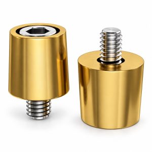
The 4 M10(3/8″) studs are specified as stainless steel. The listed stud material describes the fastening hardware, not the material of every conductive or insulating component.
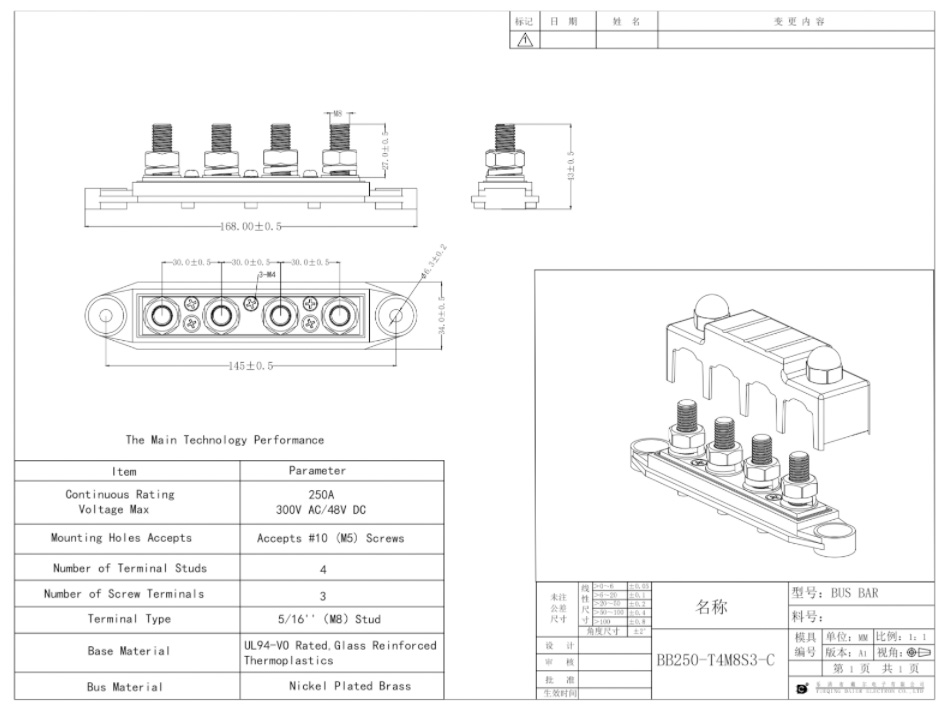
Specifications
| Model | BB400-T4M10S3-C-BR-2 |
| Current rating | 400 A |
| Maximum Voltage | 48 V DC |
| Stud terminals | 4 x M10(3/8″) |
| Screw terminals | 3 x #8 |
| Stud Material | Stainless Steel |
| Cover Material | UL94-VO Rated, Glass Reinforced Thermoplastics |
| Color Versions | Black/Red |
| Overall Dimensions | 165mm x 34mm x 42mm (L x W x H) |
Terminal counts refer to one product assembly. Color versions are not added together. Mounting screws are not counted as electrical screw terminals.
Current rating applies to the product, not to each connection. Provide circuit protection separately. Inch sizes are approximate references, not interchangeable thread specifications.
Compare Connection Layouts and Ratings
Compare this model with other connection formats in the DAIERTEK range. Matching terminal counts do not establish mechanical interchangeability.
| Model | Current rating | Stud terminals | Screw terminals | Layout reference |
|---|---|---|---|---|
| BB400-T4M10S3-C-BR-2 Current Product |
400 A | 4 x M10(3/8″) | 3 | This product |
| BB100-T2M5S5-BR | 100 A | 2 x M5(3/16″) | 5 | Mixed stud and screw terminals |
| BB150-T4M8S6-C-BR | 150 A | 4 x M8(5/16″) | 6 | Mixed stud and screw terminals |
| BB250-T4M8S3-C-BR-2 | 250 A | 4 x M8(5/16″) | 3 | Mixed stud and screw terminals |
| BB275-T4M8S6-C-BR | 275 A | 4 x M8(5/16″) | 6 | Mixed stud and screw terminals |
| BB400-T4M8S6-C-BR | 400 A | 4 x M8(5/16″) | 6 | Mixed stud and screw terminals |
Counts are totals for each listed assembly. Dual assemblies are not rated by adding two current values. Black/red options do not mean that a pair is supplied.
Common DC Connections in Practice
Typical uses for protected vehicle and onboard electrical installations.

Auxiliary power compartments
The 4 x M10(3/8″) stud layout provides a connection format for a vehicle auxiliary-power assembly. Assess the cable, overcurrent protection and installation conditions independently of the 400 A product rating.

RV and commercial vehicle electrical builds
Use within a protected electrical compartment where cable lugs need defined connection positions. Leave clearance for cable bends and access to the terminals during maintenance.
Application examples describe potential installation contexts, not verified fitment to a particular vehicle. Keep live connections protected from water, conductive debris and accidental contact.
Reference Drawing
Request Technical Documents