Group toggle and start controls in one panel
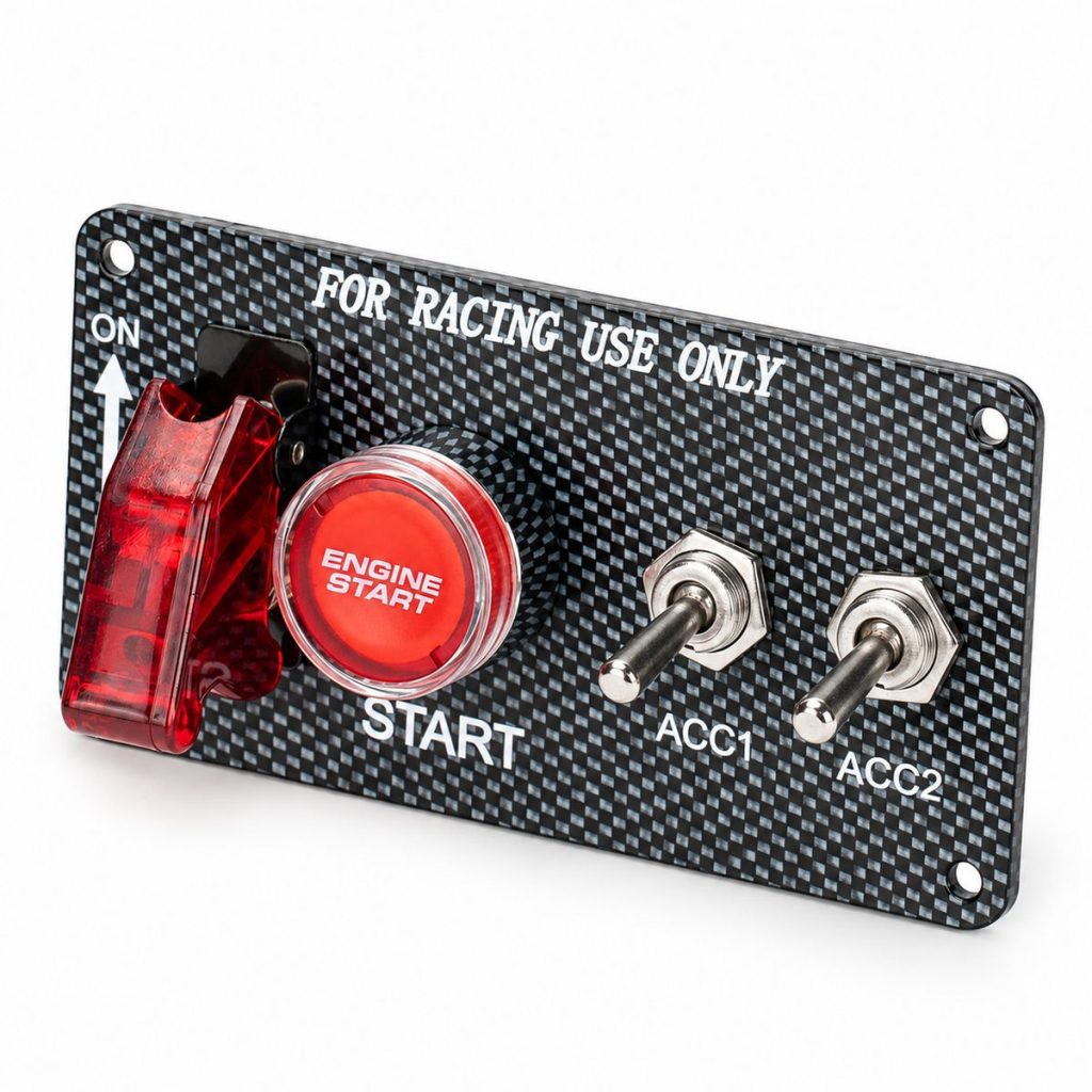
Selected PN-SAC assemblies combine covered switches, indicators and a start button. Choose the component arrangement to match the control sequence and wiring design of your equipment.
Select an ASW-B05 start-button configuration
PN-SAC2-2, PN-SAC3-2 and PN-SAC4-B05 include an ASW-B05 start button. Their accompanying toggle switches, covers and indicators differ, allowing buyers to specify a configuration by model rather than by panel appearance alone.
Choose the three-toggle configuration
PN-SAC3-3 uses three illuminated toggle switches with transparent red covers. Its supplied wiring includes 14 AWG red and 18 AWG black interconnection wires. This configuration groups three toggle controls without a listed start-button component.
Specify each control by its function
Model names identify catalog configurations. Select by the actual switch function, component count, indicator arrangement and wiring connection required for your application.
Specifications
| Product Series | PN-SAC |
|---|---|
| Product Type | Ignition-control and toggle switch panel assemblies |
| Model Families | PN-SAC2 / PN-SAC3 / PN-SAC4 / PN-SAC5 / PN-SAC6 |
| ASW-B05 Start Button Models | PN-SAC2-2 / PN-SAC3-2 / PN-SAC4-B05 |
| KN3D-101 Toggle Switch Configurations | Two switches in PN-SAC2-2; one switch in PN-SAC3-2 |
| Three-Toggle Model | PN-SAC3-3 |
| PN-SAC3-3 Appearance | Red illumination and transparent red switch covers |
| PN-SAC3-3 Wiring | 14 AWG red and 18 AWG black interconnection wires |
| Connector Supply | Included on selected catalog configurations |
| OEM Enquiries | Control layout, switch selection, markings, wiring and packaging |
Use the selected components within their electrical ratings. Connect start and accessory controls through suitable relays or contactors where required by the load and circuit design.
Applications
Automotive ignition-control projects
Group ignition and start commands in one panel for a purpose-designed vehicle electrical system. Select switching functions and relay interfaces to suit the circuit design.
Auxiliary equipment controls
Use the toggle-panel configuration to organize accessory commands, with switch covers and indicator arrangements selected for the equipment.
Custom vehicle and equipment builds
Specify a panel layout for vehicle upfitters and equipment builders that need a defined combination of switches, indicators and start controls.
Distributor and private-label ranges
Offer ignition/start and three-toggle options within one PN-SAC product family while retaining model-specific configurations.
Model Selection
| Model | Configuration | Selection Details |
|---|---|---|
| PN-SAC2 | Covered illuminated switch, start switch and toggle control | Includes matching connectors |
| PN-SAC2-2 | Two KN3D-101 toggle switches, SAC-01 cover, two WL-01 indicators and ASW-B05 start button | Separate toggle and indicator components |
| PN-SAC3 | Covered illuminated switch, metal indicator and start button | Red configuration with matching connectors |
| PN-SAC3-2 | One KN3D-101 toggle switch, SAC-01 cover, one WL-01 indicator and ASW-B05 start button | Specified component combination |
| PN-SAC3-3 | Three illuminated toggle switches with transparent red covers | Red illumination; interconnection wires, terminals and mounting screws |
| PN-SAC4 | Covered illuminated switch, metal indicator and start button | Red configuration with matching connectors |
| PN-SAC4-B05 | Covered illuminated switch, toggle control and ASW-B05 start button | Red configuration with matching connectors |
| PN-SAC5 | Covered illuminated switch, metal indicator and start button | Red configuration with matching connectors |
| PN-SAC6 | Covered illuminated switch, metal indicator and start button | Red configuration with matching connectors |
Select the model together with the required layout drawing and component arrangement. The numeric model suffix is not a specification of the number of controls.
Build Your PN-SAC Control Configuration
Send your panel layout and identify each switch, indicator and start-button position. Include the required switching functions, system voltage, connected loads, connector details and mounting requirements.
DAIERTEK can discuss compatible component selection, panel markings, wire lengths, connectors and packaging for your order. Provide artwork or a reference sample for branding enquiries.
Request a Factory Quotation for PN-SAC Series
Send the selected model, purchase quantity and intended control arrangement. Include system voltage, switch functions, indicator requirements, start-button preference, wiring diagram, mounting dimensions and packaging requirements.
Email: sales@chinadaier.com
Product: PN-SAC Series Ignition and Toggle Switch Panels