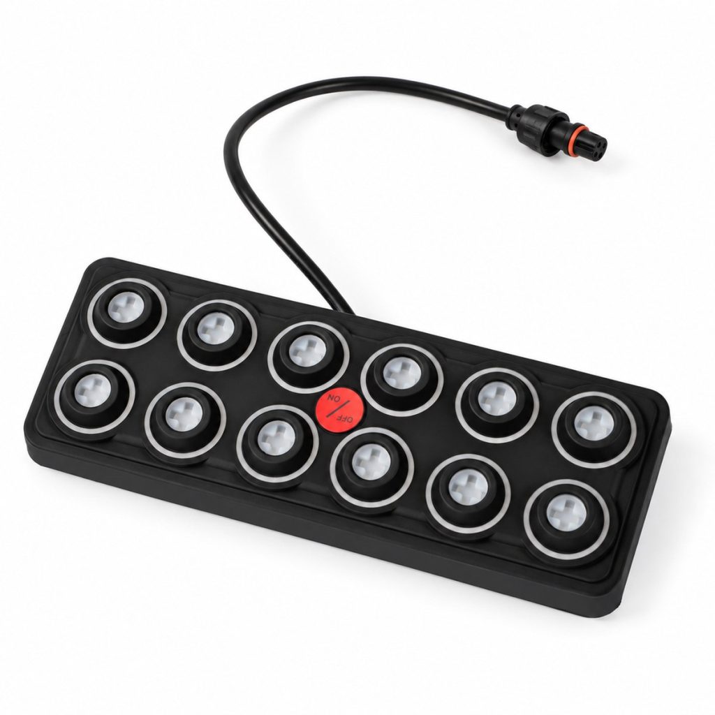
Silicone keypad design
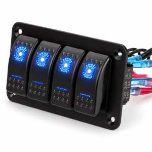
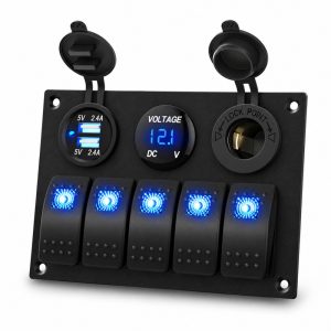
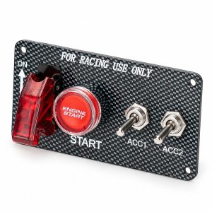
The black silicone face groups the controls within a rounded rectangular housing. The photographed panels use circular key surrounds, installed symbol button caps and a red center control. Choose the panel size and key count around the available mounting space and the number of accessory circuits.
Waterproof construction at the keypad does not define the protection of the separate control box, cable joints or the completed installation. Mount and seal each part to suit its location.
Separate control box
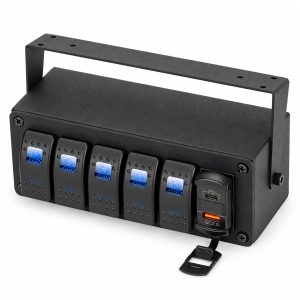
The keypad connects to a separate control box through a signal cable. This allows the operating panel and accessory connections to be positioned separately. The photographed 6 and 12 channel boxes include accessible fuse positions and terminal connections beneath a removable cover.
Select wiring and protection for the connected loads. Individual circuit fuse values and the main protection device belong to the selected assembly and must be matched to the load schedule.
Kit components
Photographed kits include a keypad, a control box, connection wiring and installation accessories. Selected kits also show an external circuit breaker, symbol labels, spare fuses, fasteners or a mounting bracket. Kit contents follow the selected model and order specification.
For an OEM quotation, provide the required channel count, mounting arrangement, cable routing and accessory load schedule so that the kit can be specified as a complete assembly.
Installation and selection
Choose the channel count before allocating accessory circuits. Check the keypad footprint, control-box space, cable path and access for fuse servicing. Specify supply voltage, each load’s running and starting current, and the required switching behavior with your enquiry.
Mount the control box and external protection where their environmental protection and service access suit the installation. Cable entries and connectors require appropriate sealing and strain relief.
Specifications
| Series | PN-RSP |
|---|---|
| Channel Options | 5 / 6 / 8 / 12 / 16 by model |
| Supply Voltage | 12 / 24V DC nominal; 8-32V DC operating range |
| Standby Current | ≤14 mA |
| Output Power | 600W at 12V / 1200W at 24V |
| Current Load | 60A system load; not a per-channel rating |
| Switch Life | 3 million operations |
| Mechanical Shock | X, Y and Z axes: 50G, 11 ms |
| Vibration | X, Y and Z axes: 10-150 Hz, 0.15 mm amplitude |
| Keypad Material | Silicone rubber with polyurethane hardcoat |
| Operating Temperature | -40°C to +85°C |
| Storage Temperature | -40°C to +85°C |
| Thermal Shock | -40°C to +72°C at 4°C/min |
| Humidity | 0-98%, non-condensing |
| UV Protection | UVB exposure: 400 hours |
| Salt Spray | Per ASTM B117 |
| Chemical Resistance | DEET, engine cleaner, isopropyl alcohol, suntan lotion, multipurpose cleaner and orange citrus cleaner |
| Ingress Protection | IP68 |
| PN-RSP5 Keypad Outline | 97 × 68 mm as shown in its dimension drawing |
Select each output circuit and its fuse for the connected load. The system current rating is not the rating of each individual output. Supply-voltage, power and protection requirements must be considered together when specifying the assembly. Protection of the completed installation also depends on its connectors, cable entries and mounting arrangement.
Applications
Boat accessory control stations
Group lighting and other compatible accessory circuits at a compact operating station, with load wiring brought to the separate control box for marine projects.
RV and camper conversions
Plan accessory switching for RV installations where the keypad can sit in the living area and the control box is mounted for service access.
Vehicle accessory projects
Use the compact silicone keypad for vehicle conversions that need multiple accessory channels with a separate load-connection box.
OEM kit specification
Select the electrical assembly and mounting locations for the actual environment and loads, then specify channel count, cable routing and kit contents with your enquiry.
Suitable for planning accessory-control installations in boats, RVs and vehicle conversions. Select the electrical assembly and mounting locations for the actual environment and loads.
Channel and Layout Selection
| Model | Control Channels | Panel Arrangement |
|---|---|---|
| PN-RSP5 | 5 | Single keypad and separate control box |
| PN-RSP6 | 6 | Single keypad and separate control box |
| PN-RSP8 | 8 | Single keypad and separate control box |
| PN-RSP12 | 12 | Single keypad and separate control box |
| PN-RSP16 | 16 | Single keypad and separate control box |
OEM Options
Discuss private-label packaging, accessory symbol sets, cable lengths, connector arrangements and kit contents with DAIERTEK. Supply your mounting-space limits, control requirements and electrical load schedule for feasibility review and a model-specific quotation.
Request a Factory Quotation for PN-RSP
Send your preferred PN-RSP model, required channel count, panel quantities, supply voltage, load schedule, cable requirements and packaging artwork to sales@chinadaier.com. DAIERTEK will prepare a quotation for the selected configuration.