Choose the Switching Response
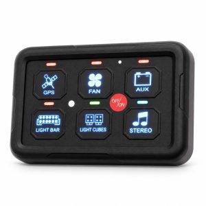
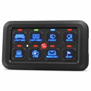
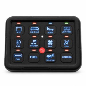
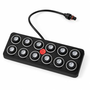
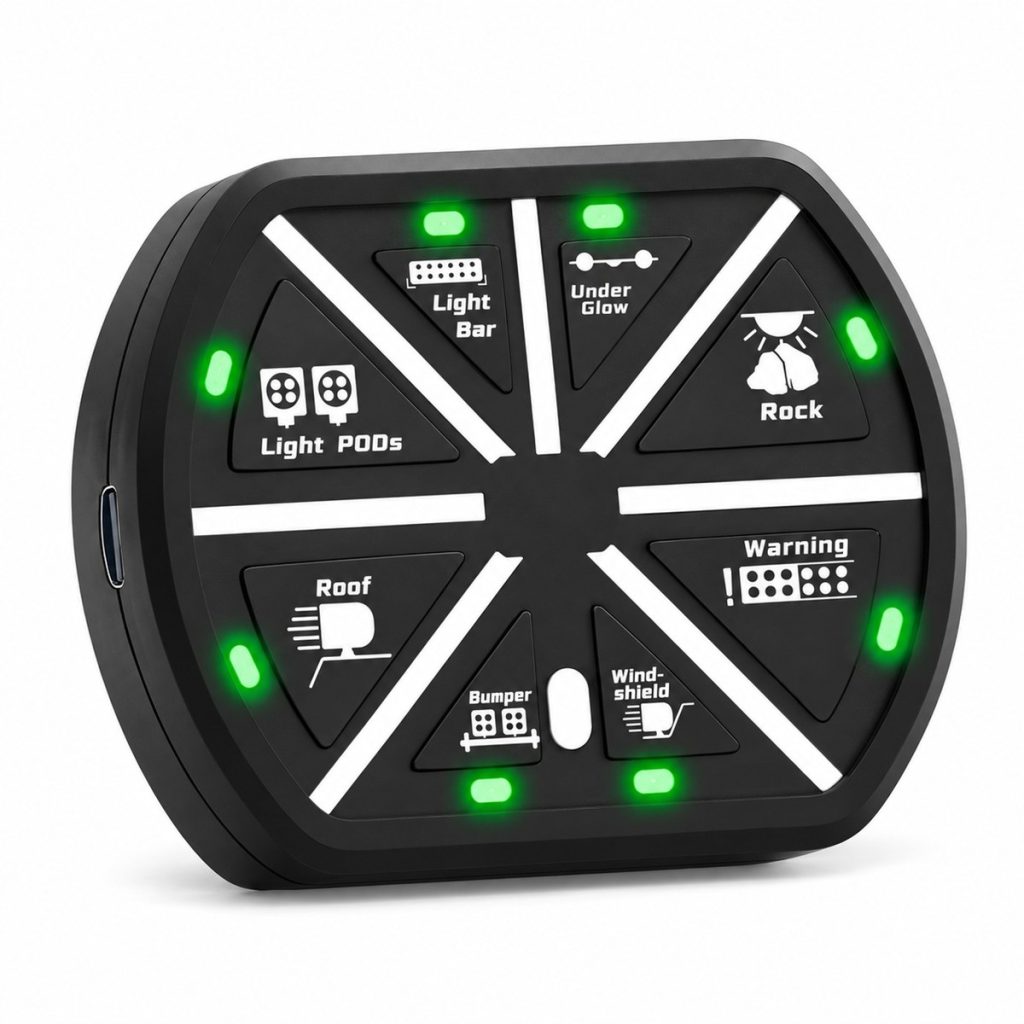
The eight sector keys provide ON-OFF control. The central control switches all outputs on or off; a long press operates the backlight. Pair the controller with its matching box using the supplied model instructions.
Identify Each Accessory
White function markings and radial separators identify the eight control sectors. Match the accessory labels to the output schedule. Choose blue or green indication as an order option while retaining the same product link.
Plan the Electrical Load
The combined system limit and each individual output limit must both be respected. A 80A system rating is not the rating of every circuit. Allocate the loads by running current, starting current and the protection required by the connected equipment.
Installation Planning
Position the power-control box where its terminals and fuses remain serviceable. Check the intended operating locations during installation. Wireless reception depends on surroundings and the position of the equipment; no fixed operating distance is specified here.
Specifications
| Accessory Outputs | 8 |
|---|---|
| Supply | 12-24V DC |
| Combined Current Limit | 80A |
| Circuit Capacity Groups | 2 × 30A; 2 × 20A; 2 × 10A; 2 × 5A |
| Switching | ON-OFF; central all-on / all-off control |
| Indicator Options | Green / Blue |
| Handheld Charging | USB Type-C |
| Handheld Battery | 300 mAh |
| Operating Temperature | -40°C to +105°C |
| Ingress Protection | IP65 |
Use the model-specific temperature and IP values in the specification table. Choose installation positions for the individual components, their cable entries and their connectors. The RF system uses its own electrical and environmental specification.
Applications
Accessory integration planning
For RV, vehicle and marine accessory projects that need a movable operating interface. Match each accessory to an output with sufficient running and starting-current capacity.
Circuit allocation review
Provide the accessory list and intended mounting environment so that circuit allocation, protection and cable routing can be reviewed together.
Mounting and cable routing
Reserve space for the panel, the control box and access to circuit protection. Plan the cable path before selecting bracket locations.
OEM kit specification
Provide the desired indicator color, function identification, kit contents and private-label packaging requirements. Include the number of kits and the load schedule for a configuration-specific quotation.
Order the Complete Assembly
Specify the rechargeable RF controller, matching box, USB charging lead, circuit protection, power wiring, brackets and function labels as a coordinated kit. Confirm the required indicator color and packaging artwork with the order.
OEM Configuration Enquiries
Provide the desired indicator color, function identification, kit contents and private-label packaging requirements. Include the number of kits and the load schedule for a configuration-specific quotation.
Request a Configuration Quote
Send model PN-SPRF8, quantity, supply voltage, accessory list, required switching logic, mounting layout and artwork to sales@chinadaier.com. Include cable-routing and packaging requirements so the quotation can describe the complete assembly.