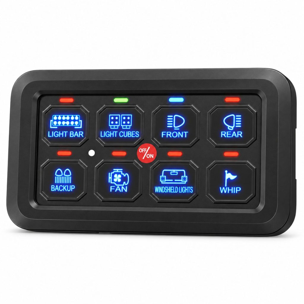
Choose the Switching Response
Assign Toggle to a compatible accessory that needs a maintained command. Select Momentary where the command should last only while operated, or Pulsed where the equipment requires a repeating output. Confirm the required logic and load behavior before allocating each circuit.
Identify Each Accessory
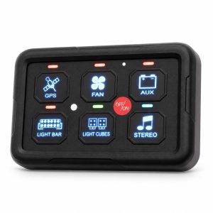
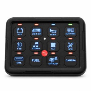
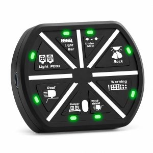
The silicone rubber keypad uses a polyurethane hardcoat. Function labels identify the connected equipment, while the RGB backlight supports visibility at the operating position. Keep the actual load list and the chosen panel labels aligned throughout assembly and servicing.
Plan the Electrical Load
The combined system limit and each individual output limit must both be respected. A 60A system rating is not the rating of every circuit. Allocate the loads by running current, starting current and the protection required by the connected equipment. Keep the stated power rating separate from the current limit.
Installation Planning
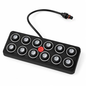
Reserve space for the panel, the control box and access to circuit protection. The panel and box mount separately. Plan the cable path before selecting bracket locations, and leave service clearance around the terminal and fuse area. The panel measurements below are overall product dimensions; they are not a cutout drawing.
Specifications
| Accessory Outputs | 8 |
|---|---|
| Nominal Supply | 12 / 24V DC |
| Input Range | 8-32V DC |
| Standby Current | ≤14 mA |
| System Current Limit | 60A |
| Output Power | 600W at 12V / 1200W at 24V |
| Switching Life | 3 million operations |
| Working Modes | Toggle / Momentary / Pulsed |
| Interface Lighting | RGB backlight; automatic dimming |
| Keypad Construction | Silicone rubber with polyurethane hardcoat |
| Operating Temperature | -40°C to +85°C |
| Storage Temperature | -40°C to +85°C |
| Mechanical Shock | 50G for 11 ms on X, Y and Z axes |
| Vibration | 10-150 Hz; 0.15 mm amplitude on X, Y and Z axes |
| Thermal Shock | -40°C to +72°C at 4°C/min |
| Humidity | 0-98%, non-condensing |
| UV Exposure | UVB: 400 hours |
| Salt Spray | Per ASTM B117 |
| Chemical Resistance | DEET; engine cleaner; isopropyl alcohol; suntan lotion; multipurpose cleaner; orange citrus cleaner |
| Ingress Protection | IP65 |
| Panel Overall Size | 115 × 66 × 14.7 mm |
| Control Box Body | 176 × 115 × 34.8 mm |
| Control Box Overall Length | 188 mm including mounting tabs |
The environmental data covers the temperature, mechanical, humidity and exposure values listed below. Select installation locations and connector sealing for the complete assembly. Salt-spray methodology is listed separately from UV exposure duration; ASTM B117 is not presented as a product certification.
Applications
Accessory integration planning
For accessory integration in RVs, boats, pickups, UTVs and off-road vehicles. Provide the accessory list and intended mounting environment so that circuit allocation, protection and cable routing can be reviewed together.
Circuit allocation review
Provide the accessory list and intended mounting environment so that circuit allocation, protection and cable routing can be reviewed together.
Mounting and cable routing
Reserve space for the panel, the control box and access to circuit protection. Plan the cable path before selecting bracket locations.
OEM kit specification
Send the required function artwork, packaging layout, cable lengths, connector needs and circuit schedule for configuration review. Specify whether the project needs the standard panel arrangement or another control interface. App and remote requirements should be identified explicitly in the enquiry.
Order the Complete Assembly
Configure the order around a matching control panel and box, signal harness, power wiring, mounting hardware, circuit-protection components and function-label set.
OEM Configuration Enquiries
Send the required function artwork, packaging layout, cable lengths, connector needs and circuit schedule for configuration review. Specify whether the project needs the standard panel arrangement or another control interface. App and remote requirements should be identified explicitly in the enquiry.
Request a Configuration Quote
Send model PN-SP8100B, quantity, supply voltage, accessory list, required switching logic, mounting layout and artwork to sales@chinadaier.com. Include cable-routing and packaging requirements so the quotation can describe the complete assembly.